
 Menu
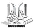
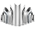
MenuPin & Bushing Service Kit - 15000
For Heavy Duty (Class 7, 8)

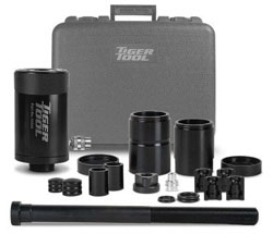
15000
While the suspension remains on the vehicle, it can service both rubber isolated bushings & threaded pins. Pin & bushing service kit are made from high grade steel w/ black oxide finish to resists corrosion.
This kit requires the use of at least one of the adapter kits listed below and a 10,000 PSI hydraulic pump to operate. Match the OEM pin and bushing number to the corresponding adapter kit required.
Features:
- 70 Percent Reduce Shop Service Times on Jobs
- Heavy Suspension Assemblies Doesn't Need to Remove
- 20 Tons of Pulling Power
- Efficient Pin Removal and Installation
- Spring Pack From the Axle Removal is no Longer Required.
- Resists Corrosion
- Black Oxide Finish
- U.S. Patent No. 8627557
Note: Use replacement parts and accessories provided by tiger tool only. All replacement parts and accessories are available. Keep hydraulic coupler protected when not in use. Dust caps should be used on couplers when not in use to avoid contaminants from entering the hydraulic cylinder and power source. This practice will help to extend the life of this product and ensure continued consistent operation.
Operating Instructions
Removing Spring Eye Pin and Bushing
- Support the truck by the chassis in an approved method so that the front suspension is unloaded.
- Support the front axle assembly so that the shackles (side bars) can be removed from the trailing end of the spring eye and chassis bushings.
- Remove the shackles from the trailing end of the front leaf springs on both sides of the vehicle. The vehicle can now be raised or the axle lowered to provide easy access to the spring eye pin and bushing.
Be aware of all other vehicle components that might be affected by this procedure such as brake lines and wiring. Ensure no damage is caused. - Place the removal split adapters over the inboard end of the pin bushing assembly - large end of the split adapter against the spring bushing. Then slide the supplied o-ring into the groove to hold them in place. The removal split adapters have an outside diameter slightly smaller than the bushing OD. The installation split adapters have an OD larger than the bushing OD. Ensure you have the smaller removal split adapters.
- Slide the retainer sleeve over the split adapters.
- Attach the pullbar to the outboard end of the spring bushing. This is done with the pullbar split adapters and pullbar retainer sleeve.
The pullbar split adapter, pullbar, and bushing pin connect together.
Place both halves of the pullbar split adapter over the bushing pin and the head of the pullbar. Now slide the pullbar retaining sleeve down the pullbar and over the split adapters. - Connect the face adapter and extension tube together and slide them over the pullbar retaining sleeve.
- Thread the cylinder tube onto the hydraulic cylinder. Slide the hydraulic cylinder/cylinder tube assembly over the pullbar, cylinder tube first.
- Thread on the retaining nut and tighten by hand until tight. This will hold everything in place. The 20 ton hydraulic cylinder will provide the power required to remove the pin bushing. Do final check to ensure all the parts are still in place—the face adapter should be flush against the spring face or the bushing housing.
- Apply hydraulic pressure—the bushing is pulled partially from the spring eye or bushing housing.
- Remove hydraulic pressure allowing the hydraulic cylinder to retract.
- Tighten the retaining nut by hand until tight to take up the slack. Check to ensure all parts are still in place.
- Apply hydraulic pressure, the hydraulic cylinder extends and the bushing is pulled fully from the spring eye or bushing housing. If the bushing is not fully removed from the spring eye or housing, repeat steps 11 through 13.
- See cross section of the bushing fully removed from the spring eye.
Installing Spring Eye Pin and Bushing
Note: Optional split adapters were used for this demonstration.
It is recommended that after removing a bushing/pin assembly, you immediately install the new bushing/pin assembly. The instructions given here follow that methodology. Note this tool pulls the bushing/pin assembly into the spring eye from the inboard side of the spring.
- Disassemble the previous puller assembly leaving the cylinder tube attached to the hydraulic cylinder
- On the bench, attach the install split adapters, o-ring, and retaining sleeve to one end of the bushing/pin assembly in the same method as step 5 and 6 removal.
- Slide the pullbar through the spring eye from the outboard side of the spring. Attach the new bushing/ pin assembly with the pullbar split adapters and the pullbar retaining sleeve in the same method as removal step 7.
- Slide the face adapter over the cylinder tube end and slide the cylinder, cylinder tube, and face adapter over the pullbar.
- Spin on the retaining nut and tighten by hand to take up the slack. Double check that the bushing/pin assembly is in alignment with the bore of the spring eye.
- Apply hydraulic pressure to the cylinder and the bushing/pin assembly is pulled partially into the spring eye. Release pressure allowing the cylinder to retract. Tighten the retaining nut and apply hydraulic pressure once again to pull the bushing/pin assembly farther into the spring eye. The install split adapters are larger than the OD of the bushing and will stop the bushing/pin assembly at the correct installation distance.
- Disassemble the tool from the bushing/pin assembly.
- Replace remaining bushing/pin assemblies as required.
Warranty Policy
Tiger Tool International Incorporated (“Tiger Tool”) warrants to its customers that cast portions of its tools are free from defects in workmanship and materials for as long as the original purchaser owns the tool.
Tiger Tool warrants to its customers that threaded areas, bolts and machined components in or of its tools will not fail due to defects in workmanship and materials for a warranty period of two years from the date of original purchase.
Tiger Tool warrants to its customers that hydraulic components will not fail due to defects in workmanship and materials for a warranty period of one year from the date of original purchase.
For warranty service a customer must return the tool freight prepaid along with original proof of purchase to TIGER TOOL INTERNATIONAL INCORPORATED.
When a customer seeks warranty service with respect to a tool and that tool is covered by a TIGER TOOL warranty, TIGER TOOL may at its option repair the tool, replace the tool or refund the purchase price for the tool.
New unused product that is returned to tiger tool as a result of the customers error or due to inventory adjustment will be subject to a twenty percent (20%) restock/rework fee with authorized RGA number otherwise a 30% restocking fee will apply.
Highly Recommended


Track Your Order

